
Note, this is an example, CoreXY machines have limited space, so a decreased print area is more likely to be seen in both X and Y dimension. The following image reflects the changes to the build area when a larger sized carriage is used on the same printer (grey is the original size, red is the decreased area as a result of a larger carriage note this is for fixed endstop positions!). Hotend dimensions are needed for your slicer (when you need to sequentially print multiple objects), firmware uses bed dimensions and positions. > Please note this is generally the most used printer convention, exceptions are applicable. When facing your printer the left to right movement is your X-axis, back and forth the Y-axis and up and down the Z-axis. The text below goes a little more in depth, first some definitions, then some theory. When you have noted the maximum sizes in X and Y direction, change the firmware and re-flash the printer board.Something similar can be done for the Y-axis.When the carriage is about to hit the frame, note the value, this is your bed X size (for a CoreXY make sure the carriage is clear over the whole Y-axis).

#E3d hemera dimensions how to
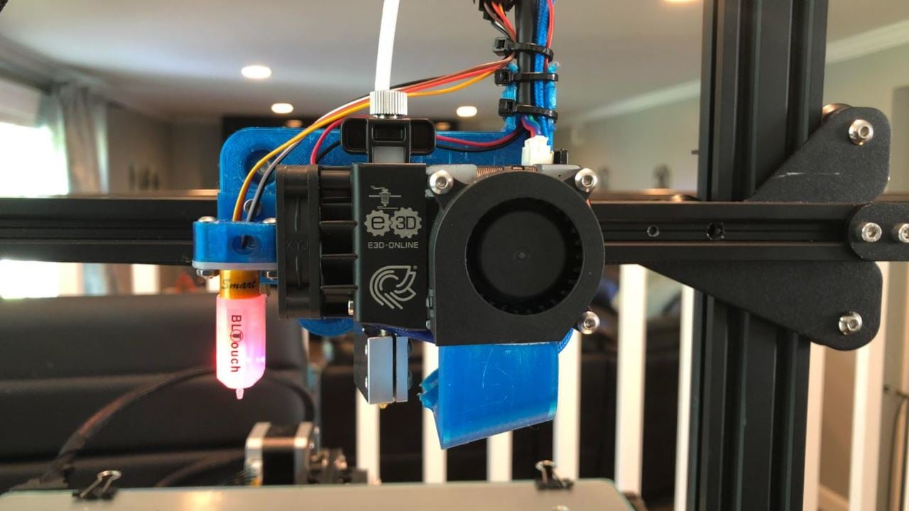
See How to center my prints on the build platform? (Re-calibrate homing offset) to set these margins correctly as you effectively need to reposition the print area on the build area. If there was enough space for the carriage, and a value for X_MIN_POS defined, this value needs to be decreased. First need to assure that the nozzle can reach the origin, if not, try to see if you can move the endstop without the carriage hitting the frame, if not possible, your left margin will be decreased.To determine the correct values (for the X-axis) you: Using a larger carriage will, if too large, diminish the printing area. In the video tutorial, I'm watching for installation they are using a different mount for their E3D Hemera, so I'm unsure how I would go about defining my own values for my setup. I'm using "Tiny Machines" firmware and my next step in the installation is defining the aforementioned parameters. I have a custom-made aluminum hot end carriage for my E3D Hemera. I'm not sure how I would measure it or at what point of reference I'm measuring from, is it from the nozzle to the edge of the hotend carriage in both the X and Y or total space on X and Y.

I see in Marlin the 'define bed size' parameters #define Y_BED_SIZE 360īut how would I go about measuring my hotend / carriage assembly to edit the values accordingly? How would I begin measuring my hotend / carriage dimensions in Marlin to prevent my hotend from slamming into the frame?


 0 kommentar(er)
